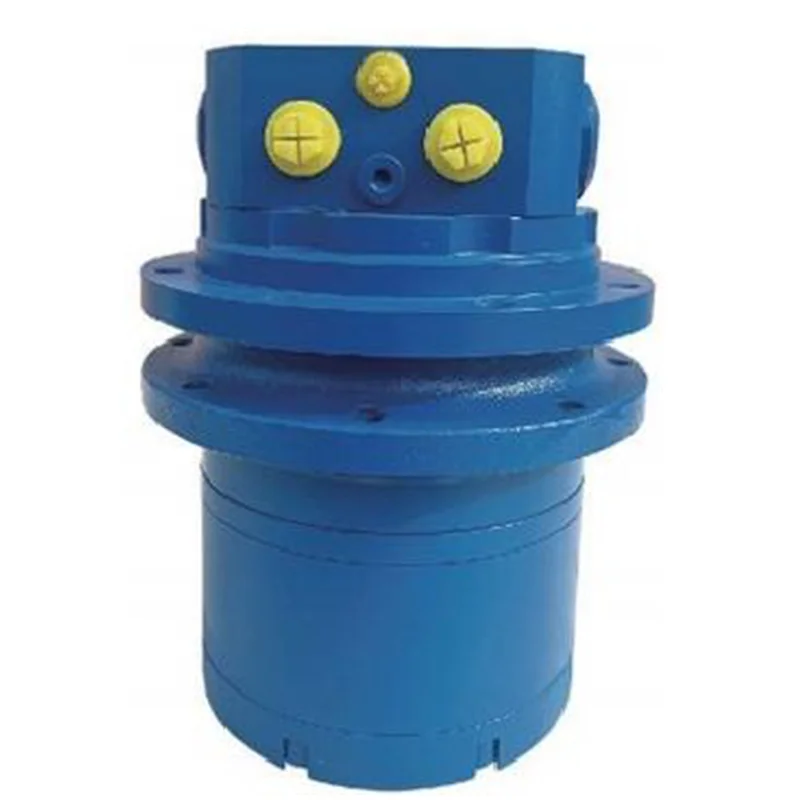
WDM Series
Tructural features:WDM series two-speed walking motor is suitable for crawler and wheeled driven vehicles and all inds of self-walking machinery,as well as winch or roller machine lifting machine.Due to the special cycloid hydraulic motor and compact structure design,the motor can be hidden in the track or wheel wide groove,or winch and roller drum simplicity;the design is
brief,the customer use space saving,the overall installation is simple.Suitable for both open and closed hydraulic loop systems.
Its characteristics:
High and low speed exchange can be achieved by hydraulic control,with a speed ratio of 1:2.
A special sealing system is used for the radial and axial sealing between the rotating body and the fixed part.
Simple in structure and easy to install.
WDM Technical Data
Displacement (LPM) | 200 | 250 | 320 | 390 | 490 |
(LPM)Max flow | 20 | 20 | 20 | 20 | 20 |
(MPa)Max pressure | 16.5 | 20.5 | 20.5 | 20.5 | 20.5 |
(N*m)Max output torque | 520 | 815 | 020 | 280 | 600 |
(MPa)2speed pilot pressure | 137Mpa | ||||
Hydraulic Schematic Diagram

WDM 2 Speed Installation Size
Facing the standard rotary direction of the motor at the output shaft shaft end
CW:Port A pressurized
CCW:Port B pressurized
Type A Flange

Type B Flange

Type D Flange

Type E Flange

Motor length gauge | |||
Displacement | L | L1 | L2 |
WDM-200 | 180.5 | 74 | 79 |
WDM-250 | 186 | 79.5 | 84.5 |
WDM-320 | 193 | 86.5 | 91.5 |
WDM-390 | 202 | 95.5 | 100.5 |
WDM-490 | 213 | 106.5 | 111.5 |
Note:
The walking motor is not filled with lubricating oil,and the illing method is as follows:
1.Remove the oi injection mouth and screw plugging,and clean the cavity.
2.Pour a proper amount of lubricating oil into the oil injection port.
Order Information Description
Position 1:Displacement 1200
2250
3320
4390
5490
Position 2:Mounting Flange
A.8-M10Ø157Ø140
8-M10 Ø157140
8-M10 circle Ø157 Flange Pilot dia Ø140 8-M10 circle Ø157 Wheel Pilot dia Ø140
B.8-M10Ø157Ø140
9-M10 Ø155Ø140
8-M10 circle Ø157 Flange Pilot dia Ø140 9-M10 circle Ø155 Wheel Pilot dia Ø140
D.8-M10Ø157Ø140
9-M10 Ø155Ø140
8-M10 circle Ø157 Flange Pilot dia Ø140 9-M10 circle Ø155 Wheel Pilot dia Ø140
E.8-M10 Ø175Ø155 8-M10 Ø180 160
8-M10 circle Ø175 Flange Pilot dia Ø155
8-M10 circle Ø180 Flange Pilot dia Q160
Position 4:Special Requirements
A Single speed
B double speed1:2
Position 6:Special Requirements
Here you can specify the special requirements required
Note:When using this ordering information,users can send the model code,displacement,flange installation size,output shaft code,oil inlet and outlet and other information to us.If the selected specification is not in the table or there are special requirements,please contact customer service or technical personnel for specific information


